VBD (Variable Buoyancy Device)
The VBD is the Seaglider's buoyancy engine and the reason it moves at all: a hydraulic system in the aft endcap that moves low-viscosity oil between an internal reservoir inside the pressure hull and an external bladder outside the hull (but inside the fairing). Pumping oil out increases the glider's displaced volume without changing its mass — it gets lighter than the water and climbs; bleeding oil back in shrinks it and it sinks. It is also the single largest energy consumer on the vehicle, so most piloting-for-endurance decisions are ultimately VBD decisions.
Source
Paraphrased from the APL-UW IOP SGX Documentation (v1.0, 2024), the manufacturer's air-bleed procedure (support correspondence, 2018), the community "Cycletron in Pupa" pump-cycling notes, IOP webinar/office hours material, and 2018–2024 field and refurbishment correspondence between Seaglider operators, APL-UW IOP and service providers (VBD rebuilds, seal failures), and 2017–2023 manufacturer support correspondence (cycletron analysis, cold-water pump rates). Hardware details vary between SG, SGX, and Deepglider variants and build years — defer to APL-UW IOP and your glider's documentation.
What's in the system
| Element | Role |
|---|---|
| Internal reservoir ("bellofram") | A rolling-diaphragm oil reservoir inside the pressure hull; its piston position is the VBD position |
| External bladder | Holds the oil that increases displacement; sits outside the hull under the aft fairing |
| Boost pump | Low-pressure pump that feeds the main pump; runs only at depth, on the ascent side (older SGs used a high-pressure boost pump with different plumbing) |
| Main pump | High-pressure axial-piston pump that pushes oil out to the bladder against sea pressure |
| Skinner valve | Magnetically latching solenoid valve that meters oil (bleeds) from bladder back to reservoir |
| Check valves (×3) | 1–5 psi valves that fix flow direction and rate within the circuit |
| Two linear potentiometers | Report the reservoir piston position; the two readings can differ by up to a few hundred counts from piston wobble, so their average is used |
Boost-pump parameters on older (non-Enhanced) buoyancy engines
Two generations of plumbing exist. Enhanced Buoyancy engines (the shallow-water-capable design) have a bypass so the main pump can run without the boost pump, plus a larger boost pump that covers greater depths alone. On engines without that upgrade there is no bypass — if the boost pump shuts off while the main pump runs, the main pump has to drag oil through the idle boost stage and the engine can be damaged. On those gliders the vendor service bulletin requires $T_BOOST,0 (boost always runs with the main pump) and $D_BOOST no greater than 5 m (boost-only operation confined to the near-surface). Know which engine you have before touching either parameter.
A few component details worth knowing
- Main pump — a commercial rotary piston pump (Hydro Leduc base) modified for the Seaglider (flats machined on the shaft for the motor coupling). Its shaft is sealed by a magnetically coupled shaft seal ("mag seal"); oil weeping from the top bearing means that seal needs replacing — see Oil leaks and the mag seal.
- Main-pump return line — carries the pump-body overflow from the low-pressure feed back to the reservoir. Air seen in it is cavitation from the pump pistons; it collects in the internal reservoir and comes out at the bleed screw (reservoir horizontal, bleed port tilted to the highest point).
- Skinner (bleed) valve — driven by a magnetically latching relay: one pulse opens it, another closes it, and it is not energized in between. The firmware has no direct feedback on valve state, so an electrical glitch that momentarily opens it goes unnoticed except through the potentiometers.
- Uncommanded-bleed detection — the firmware compares the average of the two linear-pot readings with the value after the last move; if it has drifted by more than a threshold it raises a VBD error, and the pilot's error settings decide whether the glider surfaces. One pot failing to an end stop (0 or 4095) drags the average away and triggers this falsely.
- Pot-to-pot difference — a steady gap of 200–400 counts between the two pots is normal on an older glider. The piston assembly develops a "memory" and tilts slightly as it moves, and since the full ~3400-count stroke is only about 7 cm of travel, a few hundred counts is just a few millimetres. The vendor's analysis template flags anything over 150, so judge it against the same glider's earlier tests rather than the flag.
- Pump retries in Rev E firmware (67.xx) — the Rev E code doesn't count pitch or roll retries (they always show
0in the$ERRORSline), and it no longer watches the main pump. It only monitors the boost pump when it runs alone (shallower than$D_BOOST): if the boost rate drops below ~1 A/D count per second it logs a VBD retry and switches the main pump on to help. The 66.xx code for Rev B boards tracked retries differently. - Oil volume — about 850 cc of oil is "movable"; the full fill is larger (typically ~1350 cc) because the tubes, pumps and valves also hold oil. The as-built amount is recorded on the glider's trim spreadsheet (Trim tab, aft-endcap assembly section).
Two plumbing layouts
Seagliders in the field carry two generations of hydraulic plumbing, and several pump-testing and repair decisions depend on which one you have:
| Parallel-plumbed (earlier commercial builds) | Series-plumbed (original UW, and current APL rebuilds) | |
|---|---|---|
| Boost → main | Boost and main feeds branch in parallel; the main pump can in principle draw on its own | Boost always feeds the main pump |
| Reservoir-side check valve | ~50 psi relief valve back to the reservoir | ~5 psi check valve |
| Fittings | Push-to-connect | Swage-lok |
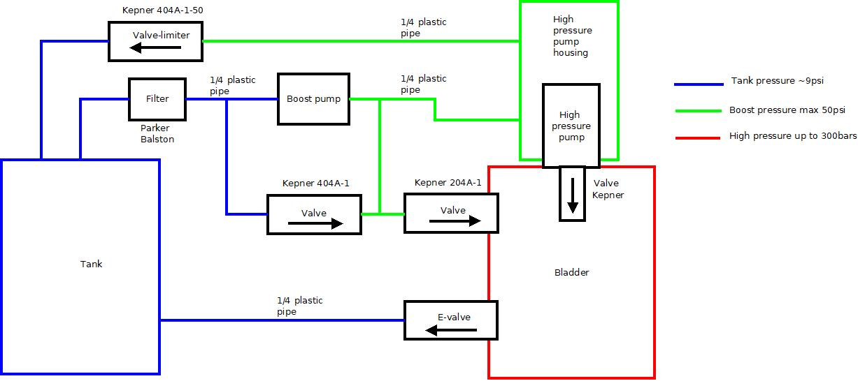
On parallel-plumbed engines, always prime the main pump with the boost
APL-UW's advice for parallel-plumbed engines is to operate them as if series-plumbed: never run the main pump on its own. With no feed from the boost line, the main pump pulls a vacuum in its own chamber, which can separate the mag seal and let oil escape into the hull. In the hw/vbd/pump dialog that means answering Y to "Use boost to prime main (old non-parallel plumbed behavior)?" — and skipping the main-only variant of the pump-cycling test below.
Which one do I have? Operators often can't tell by eye. Two ways that work:
- The trim spreadsheet. If the enhanced reservoir section of the aft-endcap assembly is filled in with component masses, the glider has the enhanced, parallel-plumbed engine.
- Photos of the endcap plumbing. Send clear photos to the manufacturer. They can identify the layout from them. In one case two older gliders that looked parallel-plumbed to their operators turned out to be series-plumbed.
Positions are A/D counts — and the names are backwards
Like pitch and roll, the VBD position is read on a 0–4095 A/D count scale, with hardware limits found at assembly and tighter software limits inside them. The conversion is $VBD_CNV = −0.2453 cc per count (same for SG and SGX) — note the negative sign:
| Hardware limit | Software limit | Volume vs. $C_VBD | |
|---|---|---|---|
| Maximum volume (bladder full) | ~105 | ~370 = $VBD_MIN | +600 cc |
| Minimum volume (bladder empty) | ~4060 | ~3960 = $VBD_MAX | −260 cc |
| Neutral | $C_VBD ≈ 2900 | 0 |
$VBD_MIN is the full bladder
Because of the negative conversion factor, small A/D counts mean large volume: $VBD_MIN (~370 counts) is maximum displacement and $VBD_MAX (~3960) is minimum. Every volmax and $SM_CC calculation trips over this at least once.
$C_VBD — the neutral position — is set for the densest water of the mission (the deepest part of the dive), and is one of the first things trimmed at sea: see Trim & Flight Model.
The VBD budget
A Seaglider has roughly 800–860 cc of usable volume change, and a mission spends it three ways:
| Total VBD available | 800 cc |
| Positive buoyancy to expose the antenna at the surface | −150 cc |
| Negative thrust in the densest water | −250 cc |
| Left over to compensate stratification | 400 cc |
The rule of thumb for what that remainder buys: about 70 cc per σT unit of density change for SGX (~50 cc for SG), so the 400 cc above absorbs ≈5.5 σT of stratification (SGX). If the mission's density range exceeds that, something has to give — shallower dives or less thrust at apogee. Driven flat out (−350 cc thrust, ~18 cm/s, full-range pumping every dive) a Seaglider can stem ~40 cm/s of depth-averaged current, but burns energy at roughly ten times the rate of a gentle mission where the VBD stays within half its range.
Energy: why the VBD dominates
Pumping at depth means pushing oil against full sea pressure — the pump accounts for about half the total energy budget of a Seaglider. The control scheme is built around this (no bleeding on descent, pumping only on the climb where the oil must be moved anyway), and the pump itself is optimized for efficiency near 1000 m — at shallow-water pressures it moves only ~2 cc/s, which is part of why shallow missions are hard on Seagliders. The most expensive single act is the big surface-maneuver pump to $SM_CC; reducing $SM_CC (where safe) and avoiding unnecessary deep pumping ($W_ADJ_DBAND, pitch-over-VBD) are the standard savings — see Trim & Flight Model.
The glider's cumulative $POWER summary in the capture file shows how lopsided this is. On one Seaglider at the end of a long mission, pumping at apogee accounted for about 84 % of all the charge drawn from the 24 V bus. Surface pumping was about 1 %, and Iridium (init, connect and transfer together) was about 13 %.
Let the boost pump do the shallow work (Enhanced Buoyancy engines only). The low-power boost pump can pump alone shallower than $D_BOOST. The vendor's advice for a glider running short of battery was:
- Set
$D_BOOSTto about 10 m at minimum, so that only the boost pump does the surface maneuver. - Where the mission allows, set
$D_BOOSTto 120 m and limit dives to 100 m. The glider then pumps on the boost pump alone. - Keep
$SM_CCand$MAX_BUOYas small as is safe.
On engines without the upgrade the service-bulletin limits in the warning above apply instead: $T_BOOST,0 and $D_BOOST ≤ 5 m.
Cold water slows the pumps
Hydraulic oil gets more viscous in cold water, so the same pump moves oil more slowly. Operators in polar and Southern Ocean water saw repeated VBD retries until they lowered the minimum acceptable pump rates. One glider used $VBD_PUMP_AD_RATE_SURFACE,3 and $VBD_PUMP_AD_RATE_APOGEE,2, and another used 4 and 3. Longer pumping also costs more charge per dive, so budget for it. Apogee pumping that takes much longer than usual in normal water is a sign of a VBD fault. It can drain the battery early.
Lab: bleeding air out of the VBD
Air in the hydraulics makes VBD moves spongy and position readings untrustworthy. The system is bled in three stages, pushing air along the path lines → bladder → reservoir → out. The procedure below uses the glider's own electronics (a jog box — a manufacturer's tool that drives the motors and Skinner valve directly — makes it easier, but is optional). Setup: connect main/boost motors and both potentiometer leads to the tailboard, tailboard to mainboard (bench alongside the endcap is fine), bench supply at 10 V and 24 V, comms cable on port A, power on, wand the glider on, and go to the hw/vbd menu.
- Lines — orient the endcap so the reservoir's "T" fitting (the pump supply line) is at the bottom: air in the reservoir floats away from the supply so the pump doesn't re-ingest it. Use the
adoption to pump to a value ~200 counts lower than currently reported (pumping pushes any line air into the bladder). Confirm the lines look clear. - Bladder — reorient so the Skinner valve (silver cylinder with the blue coil pack) is at the top — it is the bleed port back to the reservoir. Shake/rattle the bladder gently to walk bubbles up to it. Use
opento open the Skinner valve while squeezing the bladder by hand, driving air and oil back to the reservoir, thenclosewhile still applying pressure. Repeat a few times. - Reservoir — reorient with the Phillips bleed screw on top. Back the screw out slowly, a couple of turns only — the linear-potentiometer springs keep the reservoir pressurized, and trapped air is forced out. When oil (not air) starts to emerge, re-seat the screw fully.
Don't remove the bleed screw
The reservoir is under spring pressure. If the bleed screw comes out too far — or all the way — oil squirts out with no way to stop it except plugging the hole. A couple of turns is all it takes.
Repeat any stage as needed; one full pass removes virtually all the air.
Lab: cycling the pumps ("cycletron")
Exercising the VBD through full-range cycles on the bench — main pump alone, main + boost, and boost alone — verifies pump health and produces a logged dataset (currents, rates) to compare against previous services. The community procedure runs from the glider's hw/vbd/pump menu with a terminal log capturing everything:
- Start a terminal log (e.g.
sgXXX_cycle_main_only_YYYYMMDD), wand on, and enterhw/vbd/pump. - Answer the prompts: specify A/D counts (not pressure); accept the software min; 5 s rest; accept the software max; 5 s rest; then the
D_BOOST/ "use boost to prime main" questions per the variant you are testing (both N for main-only; prime Y for main+boost). - Sample interval 1 s, display readings Y, 10 cycles, 900 s pump time. Close the log when done.
- For boost-only, first set
$D_BOOST,25(saved to NVRAM) and re-zero the pressure sensor at sea level (hw/pressure/sealevel) so the glider believes it is deep enough to run the boost pump, then run the same cycle dialog answering Y toD_BOOST. Restore the operational$D_BOOSTafterwards (see the boost-pump parameter warning above).
Main + boost is the run that matters
On a series-plumbed engine, either pump running alone has to push or pull oil through the idle pump, so single-pump runs give rates you will never see in the field. The manufacturer's advice for these engines is to run only the main + boost cycle. On parallel-plumbed engines, main-only is ruled out for mag-seal reasons (above). Either way, main + boost is the test to trend from service to service.
If the cycle refuses to start
If the current VBD position sits slightly above the default software max, the cycle won't start — either enter the current position as the max, or first move the VBD by A/D counts to below the max.
The logged HVBD lines can be bookmarked (e.g. in Notepad++), extracted, and pasted into a spreadsheet to trend pump rate and current draw over time.
Before you start
- Pull a proper hull vacuum first. The internal vacuum helps draw oil back into the reservoir; cycling an open or unevacuated hull gives unrepresentative results. Bring a vacuum pump and the pressure-relief valve tool when testing at someone else's lab.
- Skip main-only cycles on parallel-plumbed engines (see Two plumbing layouts).
- Very old firmware (e.g. 66.06) may not offer the boost-pump questions at all.
- On bench power, use a supply that can deliver the main pump's peak current, set to the glider's battery voltages (10/24 V or 15 V; check which one the VBD is built for). On one glider a current-limited supply let the bus sag below 4 V while the main pump ran. The pump crawled, the TT8 browned out, and files on the CF card were corrupted. With the supply limit raised, the bus still dipped to about 10 V and pump rates stayed low. Run at least one self-test on the glider's own batteries before trusting the numbers.
Reading the output
Newer firmware (Rev E) prints one line per sample under the header cycle sec vbd0 vbd1 avg mA P psi rate effic motors volts:
| Column | Meaning |
|---|---|
vbd0, vbd1, avg | The two linear-pot readings and their average (A/D counts) |
mA | Pump current |
P, psi | Pressure-sensor counts and the same converted to psi |
rate | Pumping rate in A/D counts per second |
effic | Hydraulic efficiency (hydraulic power out vs. electrical power in) |
motors | Two digits for the boost and main motor state (10 = boost only, 11 = both) |
motorP (where present) | Pressure as read by the motor controller's own ADC |
The manufacturer's analysis spreadsheet has one tab each for pump and bleed in the main, main + boost and boost variants. It flags lines where the linpot difference is over 150 counts, the rate is under 1.2 counts/s or the current is over 500 mA, and summarises average, minimum and maximum current, rate and linpot difference for each variant. For scale, here is an older series-plumbed glider on the bench under vacuum, judged healthy by the manufacturer after a bladder change:
| Variant | Avg current | Avg rate | Avg linpot difference |
|---|---|---|---|
| Main + boost, pumping | ~430 mA | ~2.5 counts/s | ~205 counts |
| Boost only, pumping | ~40 mA | ~2.5 counts/s | ~205 counts |
The main pump is also clearly louder than the boost pump, so you can hear which one is running. If a main-only or main + boost run shows the motor current staying around 40–65 mA and the A/D reading not moving on the pump lines, only the boost pump is running. After reassembly, check that the main-pump motor connector (J4) is seated. In one case that was the whole fault.
What matters is how current and rate compare with the same glider's earlier tests (or a healthy sister glider). A newly built vehicle that showed roughly double the usual current at about half the usual rate was judged unfit to deliver: it would still pump, but endurance would suffer badly and it pointed to a VBD fault. It went back for a rebuild.
Oil leaks and the mag seal
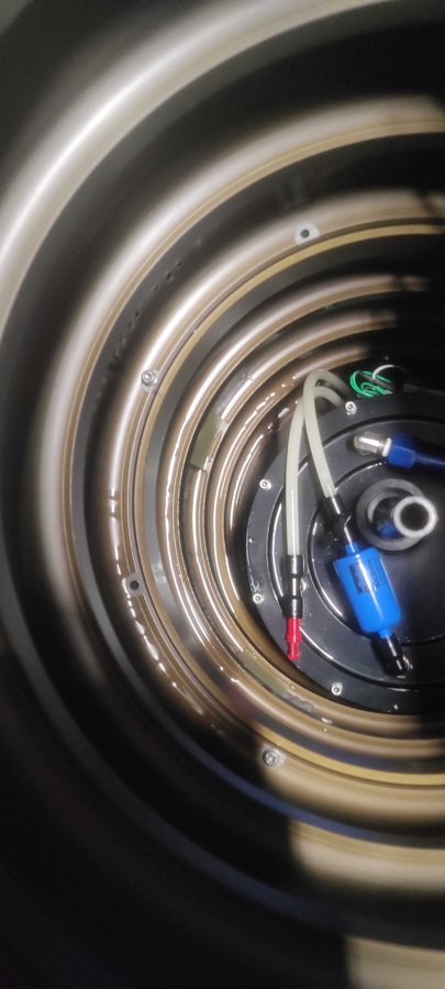
Oil appearing inside the aft endcap or the hull almost always comes from the main pump's mag seal:
- The mag seal "burps" — momentarily unseats and lets a little oil past — when the piston is over-pumped into the reservoir cylinder head at the extremes of travel, or when the main pump runs without a boost feed. It often reseats itself once oil starts flowing back. After a burp the software limits are commonly pulled in a little from the extremes (one example after a ~5 cc leak:
$VBD_MIN340 → 390,$VBD_MAX3600 → 3550). - A glider that shows oil in the endcap but then passes a pressure-chamber test (assembled, to ~1000 psi, no uncommanded bleeds) is probably fine — but a momentary loss of seal at the wrong moment can end a mission. Tell the owner. One operator pulled such a glider from a long deployment rather than accept the risk (and noted that a known, disclosed risk may also affect an insurance claim).
- A mag seal that keeps leaking should be replaced. The durable fix is APL-UW's mechanical shaft seal upgrade. The manufacturer also offered its own replacement seal for the legacy mag seal. Either swap is depot work, not a field job.
- The mag seal is finicky and only works if it is set perfectly. Running the main pump with air in the system strains it and can force the seal faces apart. That is why the manufacturer's advice is to change it whenever the VBD has been opened. If a leak is found and the pump hasn't been run since, the seal may still carry on working. When in doubt, replace it.
- Unexplained oil loss can also show up only in some tests — in one case main-only cycles were clean, but a boost-only run lost ~90 cc. Log where and when oil appears (check after every stage) before deciding what to replace.
A failing bleed path can take electronics with it: on one glider, parts of the main board around the VBD drive failed while the oil-return valve was misbehaving. After replacing the board components, the pump was cycled for hours under full vacuum to confirm the fix.
Before deployment
- Check the software limits in the glider, not just on paper. On one glider a temporary
$VBD_MINof 1400 (set during earlier trimming) was never reset to its normal ~600. The glider sat low at the surface with much less pumping range than intended, and comms suffered. - If the glider has been opened, check that the internal cables (one case: the pitch cable) are routed clear of the mass-shifter gears before closing up.
- Treat a pot reading pegged at 0 or 4095 as a no-go. One glider logged 4095 on a linear pot during its first dive, recovered on the next, and was then lost after its second dive. The cause was never found, but in hindsight the pegged reading was the warning to act on.
- Anything mounted in the aft fairing must clear the fully inflated bladder. For example, a PAM recorder housing sits with its connector end toward the bladder, placed just aft of the bladder at full inflation so the two never touch. Route its cables clear of the bladder too. Don't overtighten the plastic cradle screws. A housing that works loose can also upset the glider's flight (in one case, uncommanded pitch changes on the climb).
See also
- Trim & Flight Model —
$C_VBDtrimming, volmax estimation in the tank, and the FMSvbdbiasestimates that track volume through a mission. - Dive Cycle & Control Files — where pumps and bleeds happen in the dive, and the parameters that bound them.