Rechargeable Lithium-Ion Batteries
Procedures for charging and querying the Teledyne Webb Research (TWR) rechargeable lithium-ion smart battery packs used in Slocum G3 gliders.
Source
Organized from the TWR guide "Rechargeable Lithium Ion Batteries: Procedures for Charging and Querying" (Rev. 2022-09-06). This is a condensed reference — defer to the official Teledyne documentation for your specific glider.
Hardware Overview
The rechargeable packs are smart batteries: each communicates over a set of channels, addressed as $R,0 through $R,3.
| Pack | Channel(s) | Location |
|---|---|---|
| Aft pack | $R,0 (Channel 0) and $R,1 (Channel 1) | Aft section |
| Pitch pack | $R,2 (Channel 2) | Forward section |
| Extended energy bay pack | $R,3 (Channel 3) | Energy bay (if installed) |
Channel assignment is not always consistent
A pitch or extended energy-bay pack registers as Channel 2 ($R,2) or Channel 3 ($R,3) depending on the cable it is connected to. If no extended energy bay is installed, Channel 2 or Channel 3 will simply not respond.
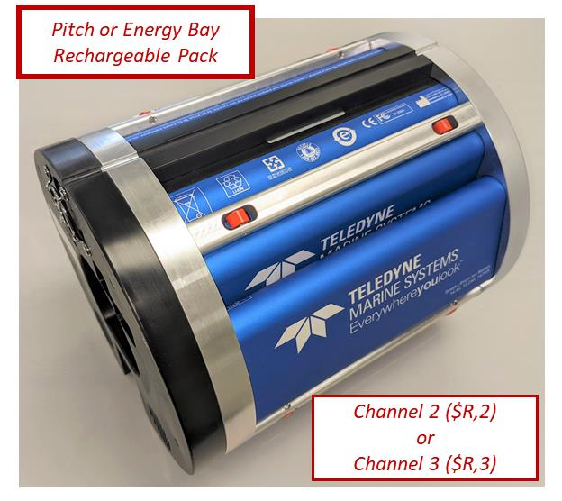
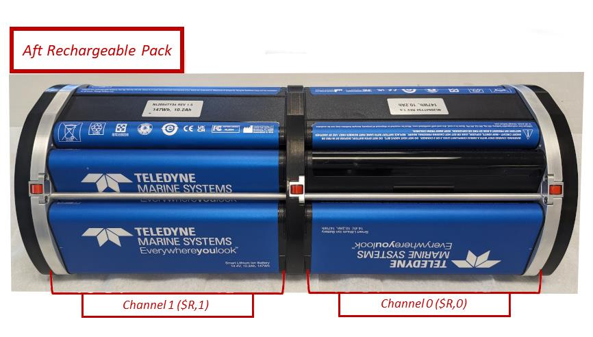
$R,0) and Channel 1 ($R,1). 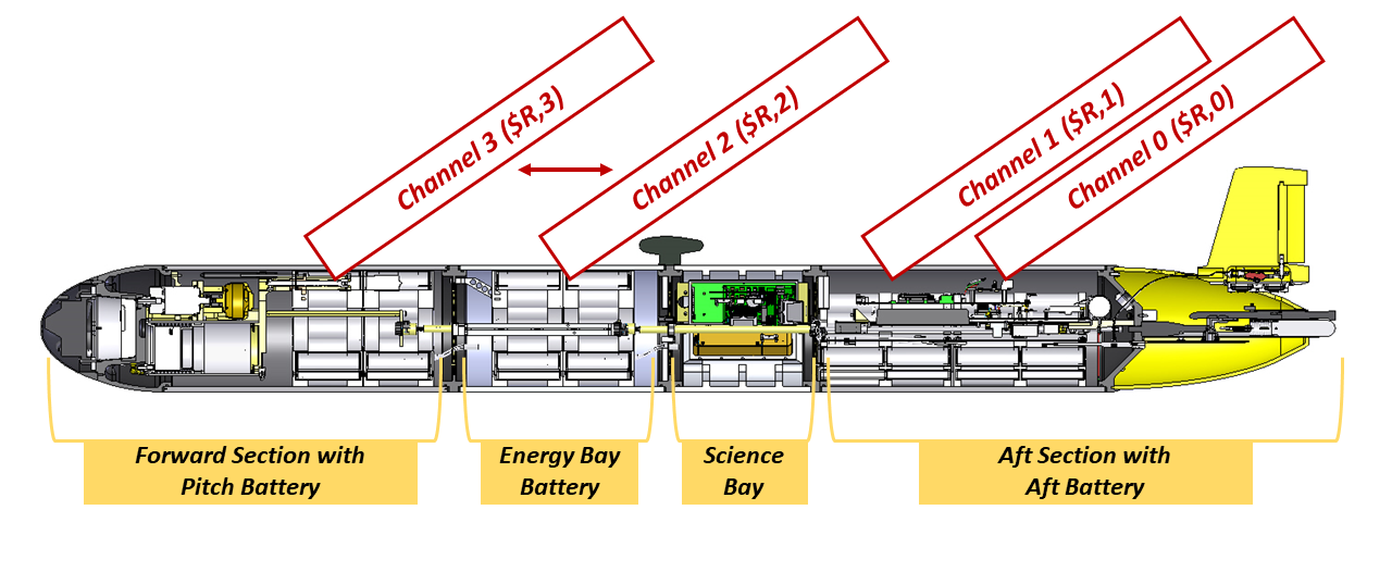
Charging Equipment
| Item | TWR part number |
|---|---|
| Battery Charger ("Charging Box") | 305839 |
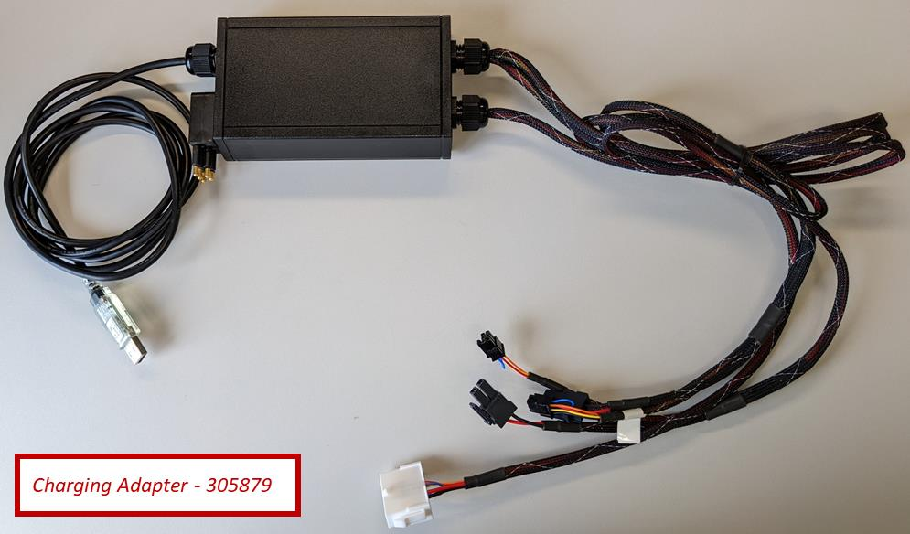
| Battery Charging Adapter | 305879 |
| Charging port jumper | LPIL-5 |

Charging Procedure — Batteries Installed in a G3 Glider
Powering on while charging
The glider may be powered on while charging, but use caution running simulations or bench tests — power-related data may not be reliable during charging.
- Remove the aft tail cowling.
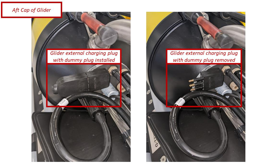
- Remove the LPIL-5 dummy plug from the charging port and set it aside.
- Connect the battery charger (P/N 305839) to the charging port using the LPIL-5.
- Plug the charger into a 110 V AC outlet.
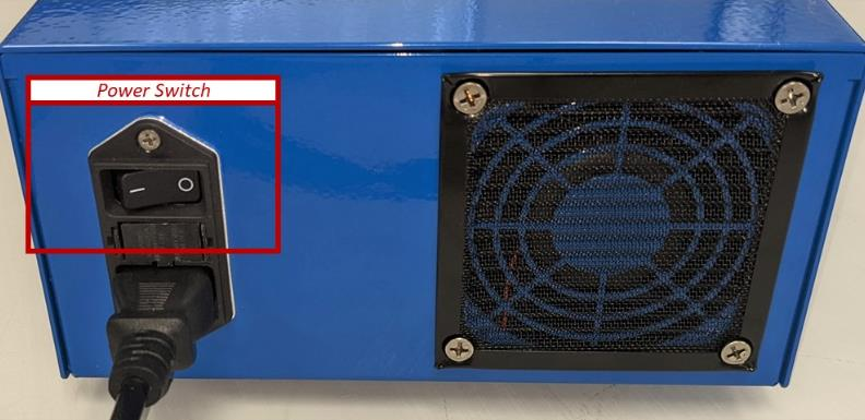
- Turn the charger on with the rocker switch above the AC power cord.
The batteries will begin charging.
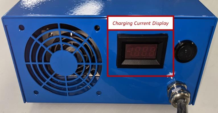
Reading the charge current
The charger display shows charge current, which varies as it establishes communication with the packs:
- Initial draw of ~1 A rises to ~12 A (standard configuration) or ~17 A (extended configuration) within a minute or two, then stabilizes.
- A nearly discharged battery draws slightly less than a full one.
- Charging cables may feel warm to the touch — this is normal.
- As each pack finishes, the current drops. When all packs are charged, the current settles around 0.5 A.
Charging Procedure — Batteries Removed from the Glider
Requires the charging adapter
This method uses the Battery Charging Adapter (P/N 305879).
- Remove the batteries from the glider. For pitch and energy-bay batteries, disconnect the pitch battery cable from the battery and leave the cable in the glider.
- Connect the charging adapter to the battery. The adapter can charge one aft battery and two pitch batteries simultaneously — the connections are keyed.
- Confirm the battery charger is off.
- Connect the battery charger to the charging adapter.
- Plug the charger into a 110 V AC outlet.
- Turn the charger on with the rocker switch above the AC power cord.
Charge-current behavior is the same as the installed procedure above (~1 A rising to 12 A / 17 A, settling near 0.5 A when complete).
Querying the Batteries — Installed, via SFMC
Lab use only
Put the glider into Shell only in the lab over Freewave — never on a deployed glider.
Note
Batteries can be queried while charging.
- Power on the glider and connect to it via Freewave on a mobile dockserver running SFMC.
- Put the glider into Shell.
- From GliderShell, type
talk batteryand press enter. - In SFMC, switch to the serial perspective terminal (different from the normal SFMC communication path):
- Click the Configuration tab → System Status.
- Under Dock Server Ports, find the green square for the USB port the glider is on, then click the terminal (
>_) icon next to it to open the serial perspective.
- Query the packs with the commands below, pressing enter after each.
Commands are case-sensitive
| Command | Pack |
|---|---|
$R,0 | Aft pack — Channel 0 (note: Batt #1 on $R,0 is empty) |
$R,1 | Aft pack — Channel 1 |
$R,2 | Pitch pack — Channel 2 |
$R,3 | Extended pack — Channel 3 |
The aft pack has two separate channels — query each to get data from the full pack.
Tip
Expect to run each command several times to collect data from all cells in a pack. More repetitions may be needed while the batteries are charging.
Querying the Batteries — Direct Connection
Requires the charging adapter
This method uses the Battery Charging Adapter (P/N 305879). Batteries can be queried while charging.
- Remove the batteries from the glider.
- Connect the charging adapter (305879) to your computer via USB.
- Open a terminal emulator such as TeraTerm or Procomm.
-
Connect to the USB serial port with these settings:
Setting Value Baud rate 115200 Data 8 bit Parity none Stop 1 bit Flow control none -
Query the packs with
$R,0…$R,3(case-sensitive), as in the SFMC method. The channel a pitch/extended pack answers on (2 or 3) depends on the cable it is connected to.
The aft pack has one empty cell by design
$R,0 Batt #1 is an intentional dummy cell. When queried it always returns status 0x210 with no information — this is normal.
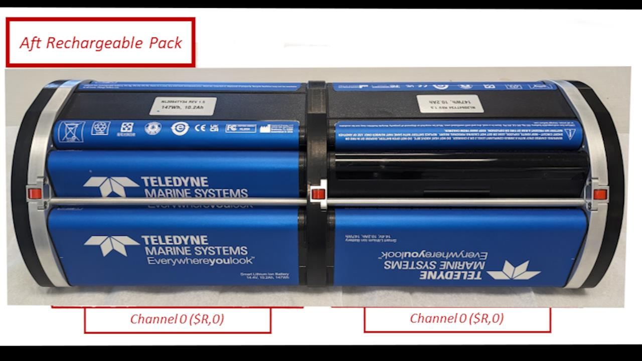
$R,0 Batt #1.Reading the Query Output
A single cell of a pack returns a block like this:
Batt #: 0
Status: 0xcc50
LTCO: 0x202
Voltage: 14551 mV
Current: 756 mA
Temperature: 298.101562 K
Serial: 1533
Remaining Capacity: 3685 mAh
Full Charge Capacity: 9876 mAh
Time to full charge: 508 min
Cycle Count: 4
Thermistor (raw): 32512
Thermistor (V): 2.480528
Manufacturer Name: INSPIREDE
Device Name: NL2054HD34
Device Chemistry: LION
Decoding the Status word
Status is a 16-bit value reported in hexadecimal. To interpret it, convert the four hex digits after 0x to 16 binary bits (e.g. with the Windows Calculator in Programmer mode, or an online hex-to-binary converter).
Example: 0xcc50 → 1100 1100 0101 0000. Reading the bits left to right as positions 1–16, the bits that are on are 4, 6, 10, 11, 14, 15.
This is the charger IC status — not the cell's state of charge
These bits report the status of the charging integrated circuit for each battery, not the battery's charge level.
| Bit | Flag | Bit | Flag |
|---|---|---|---|
| 1 | AC_PRESENT | 9 | VOLTAGE_OR |
| 2 | BATTERY_PRESENT | 10 | CURRENT_OR |
| 3 | POWER_FAIL | 11 / 12 | LEVEL_3 / LEVEL_2 |
| 4 | ALARM_INHIBITED | 13 | CURRENT_NOTREG |
| 5 | RES_UR | 14 | VOLTAGE_NOTREG |
| 6 | RES_HOT | 15 | POLLING_ENABLED |
| 7 | RES_COLD | 16 | CHARGE_INHIBITED |
| 8 | RES_OR |
SafetySignal resistance flags
- RES_UR — resistance under range: SafetySignal resistance < 575 Ω.
- RES_OR — resistance over range: SafetySignal resistance > 95 kΩ.
- RES_HOT — SafetySignal resistance < 3150 Ω (hot battery). Set whenever RES_UR is set.
- RES_COLD — SafetySignal resistance > 28.5 kΩ (cold battery). Set whenever RES_OR is set.
Battery Life, Warranty & Shelf Life
Manufacturer specifications (Inspired Energy)
- Life expectancy: ~6174 mAh after 300 charge/discharge cycles under normal storage and use (charge phase CC/CV 4000 mA, 16.8 ± 0.05 V; discharge 2040 mA down to 2.5 V/cell at 25 °C).
- Warranty: one (1) year from date of shipment from Inspired Energy against defects in workmanship, material, and construction.
- Shelf life: shipped at 20–30 % rated capacity, giving a minimum 6 months shelf life at 25 °C. Higher storage temperatures shorten this — recharge periodically.
Deep-discharge shutdown
To prevent parasitic drain, the electronics enter a shutdown mode if any cell voltage drops to ≤ 2300 mV. Recovering from this requires an initial low (pre-charge) to reactivate the electronics before normal charging. Any SMBus v1.0+ compatible charger can supply this pre-charge.
Field Notes: Capacity, Discharge & Checkout
Source
Operator experience from the UG2 community Slack. These are real-world observations, not specifications — defer to TWR for authoritative numbers.
Discharge behaviour
- Recommended config is roughly
f_coulomb_battery_capacity215 Ah (standard) / 300 Ah (extended), with an undervolts abort around 12–12.8 V. - Unlike lithium primary packs, the rechargeables have little or no real "shelf." Voltage falls fairly linearly toward ~12.2 V, then drops steeply, with the electronics shutting off near 10 V. Set undervolts conservatively and don't count on a shelf to fly home.
At 10 V the pack shuts off — and stays off for ~32 hours
The protection circuit hard-disconnects the pack near 10 V. Once that happens the glider goes dark, and you then wait roughly 32 hours for the independent emergency circuit to wake the vehicle into emergency mode (and Argos) — a long gap with no Iridium and no console. Because the drop from ~12.2 V to 10 V is steep and there is no shelf to fly home on, set undervolts high enough to leave margin for your full recovery window rather than chasing the last amp-hour. This has already caught at least one G3 operator.
- Discharge rate matters. Usable capacity depends heavily on how hard you pull the pack — bench-testing an extended pack to a 12 V cutoff at a continuous 6.7 A (≈1000 m pumping draw) yielded ~309 Ah, versus ~285 Ah when the same pack hit the 12 V undervolts on a real mission; dropping to 2 A and a 10 V cutoff squeezed out ~326 Ah. Test at realistic mission rates, ideally after a mission to find the true endpoint.
- Real-world reference: three consecutive 30-day missions (recharged overnight between) each drew ~140 Ah, starting near 16.2 V and ending 14.0–14.4 V.
Pre-deployment checkout
- Always verify communication with every pack as part of checkout — query via
talk battery(see above) and confirm all cells respond. - The aft pack's aft connector latch tends to come loose or break during assembly — a frequent cause of a pack that won't talk or that drops voltage early.
- The energy-bay and pitch battery wiring harnesses look identical but are not — a swapped harness has caused garbled/absent pack output and unexplained capacity loss. Confirm the right harness on the right pack.
- As with primary packs, re-check the compass (four-point check) after installing batteries.
Mainboard H-bridge clearance
With lithium-ion packs the clearance between the underside of the main board (pump H-bridge) and the battery hardware is tight. Battery bracketry can rake the board during assembly/disassembly and damage the pump H-bridge FET — symptoms include the glider beeping and resetting when retracting the ballast pump (extend still works). Seat packs carefully and watch that clearance.
G2 vs. G3 wiring
- On a G3, rechargeable packs connect to the lithium circuit — the glider powers on as soon as the battery is connected.
- On a G2, rechargeables typically connect to the alkaline circuit instead. The Li-ion pitch pack also sits further forward of the ACME nut, so the pitch-motor calibration may need adjusting.
See Lithium safety on vessels for charging, fire, and transport precautions that apply to these packs.